
48V Ebike Controller Wiring Diagram Wiring Diagram Schematic
Altium Designer:https://www.altium.com/yt/electroniclinicRead Instructables:https://www.electroniclinic.com/500w-ebike-brushless-motor-controller-wiring-expl.

Electric Bike Controller Wiring Diagram
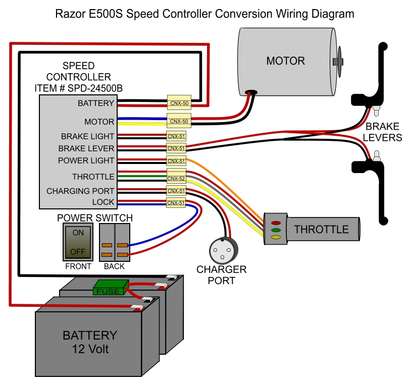
The components of a 48v e-bike wiring diagram include the battery, motor, controller, and throttle. All of these components are connected to one another via the wiring harness. The battery is the power source for the e-bike, and it is connected to the motor and controller.

48v Ebike Battery Wiring Diagram
1. Ensure You Have The Power Connectors Set Up Properly The power connector has 3 wires; the two large wires are the positive (red) and negative (black) wires. The smaller wire is a switch that turns on the circuit when connected to the positive and shuts down the circuit when connected to the negative.

E Bike Controller Wiring
The 48V e-bike controller wiring diagram is a visual representation of how the electronic components of your bike are connected. This includes the motor controller, battery, throttle, speedometer, brake lights, and other accessories.

48v Ebike Controller Wiring Diagram Wiring Harness Diagram
Understanding the wiring diagram of an ebike controller is essential for anyone looking to build or customize their own electric bike. In this comprehensive guide, we will walk you through the step-by-step process of understanding and deciphering an ebike controller wiring diagram.

Ebike Controller Wiring Diagram
48v Controller installation, E-Bike conversion Kit. Installation.Rear Hub E bike Conversion Kits https://augustineebikes.com/hub-conversion-kitsFront Hub Co.

48V Electric Scooter Wiring Diagram and V Electric Bike Controller Wiring Diagram Wiring
The diagram should always be read from left to right, with each component being labeled and connected to the next component in the chain. This will help you identify which parts need to be connected, and in what order. Identifying Connectors in an Electric Bike Controller Wiring Diagram

Ebike Controller Wiring Diagram
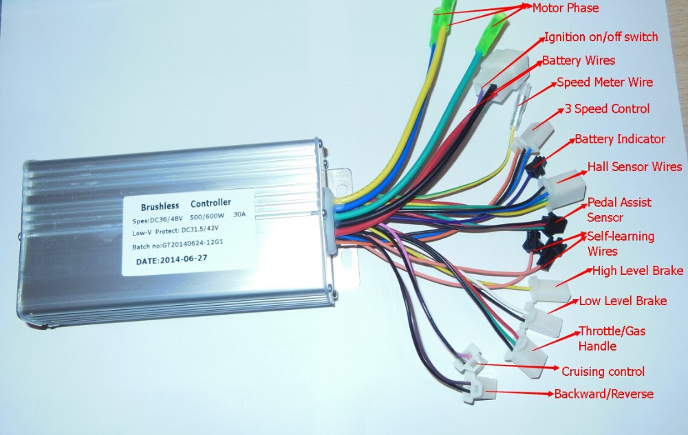
With this diagram, a user is able to quickly and easily install, wire, and connect their motor to a variety of controllers that run on 48 volts of power. This makes it easy to power brushless motors in applications such as drones, robotics, or industrial machinery. The wiring diagram was designed with convenience and efficiency in mind.

e bike motor wiring diagram
48V 1000w controller wiring diagrams provide detailed instructions for connecting the components of a 48V 1000w controller, such as power sources, switches, and output devices. These diagrams help electricians and DIYers alike to understand how the controller should be wired.
Electric Bike Controller Schematic Wiring Diagram Image
1. Get the right tools and materials. You'll need a soldering iron, wire strippers, electrical tape, and a variety of crimp connectors. 2. Gather all the components of the e-bike controller. Make sure you have everything needed to assemble the controller. 3. Create a schematic diagram.

48v Ebike Controller Wiring Diagram Wiring Harness Diagram
48/72V Brushless controller wiring diagram? *Please help* trophix Dec 12, 2018 trophix 10 mW Joined Dec 12, 2018 Messages 23 Dec 12, 2018 #1 Hey everyone, I'm sorry if this question has been answered before but I'm new here and I'm trying to upgrade my controller for faster speed.

48V Ebike Controller Wiring Diagram Wiring Diagram Schematic
The components of a 48 Volt 48v E Bike controller wiring diagram consist of the main power cable, the ground cable, the throttle cable, and the power switch. The power cable is usually the largest wire and is usually the red wire. The ground cable is usually the black wire and is the connection for the ground of the system.
[DIAGRAM] 48v Electric Bike Controller Wiring Diagram
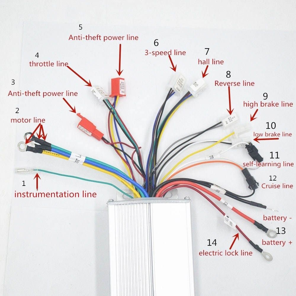
The wiring diagram of a 48V e-bike controller provides a simplified guide on how to connect the various components correctly. It outlines the connections between the motor, battery, throttle, brake sensors, and other essential elements.
Electric Bike Controller Wiring Diagram Wiring Diagram
The core function of an electric bike controller is to take all the inputs from all the electric components ( throttle, speed sensor, display, battery, motor, etc.) and then determine what should be signaled in return to them (motor, battery, display).
Understanding The Basics Of A 48V EBike Controller Wiring Diagram Moo Wiring
The 48V e-bike controller wiring diagram is an essential ingredient for any electric bike. The wiring diagram is the blueprint to install, maintain, and repair the e-bike controller. This diagram provides crucial information about the battery, throttle, motor, and other components of the e-bike. The diagram can be utilized by both professional.

48V Ebike Controller Wiring Diagram Wiring Diagram Schematic
Watch Video Tutorial: 500W Ebike BLDC Motor Controller, Description: 500W Ebike Brushless Motor Controller wiring explanation, Hoverboard Motors Test- In this article, you will learn how to use this 36V to 48Volts 500W Ebike or Electric Bike Brushless Dc Motor Controller with the Hoverboard 350 Watts BLDC motors.
